2019-06-19 Successstory, Company
The inner values count
No product stands for KRIWAN as much as the INT69. The standard for motor protection in refrigeration systems has made KRIWAN great. Thanks to the INT69, KRIWAN has become an international expert in motor protection over the last five decades and today offers hundreds of different INT69s - always for the precise application. In order to guarantee precisely this precision in development, the most important components are manufactured by KRIWAN directly on site in Forchtenberg.
“We rely on quality production made in Forchtenberg. We keep production in our own hands so that we can reliably supply the INT69 in a wide variety of configurations and in the required quantities: We have a machine park perfectly set up for the production of INT69 components and the corresponding machine operators who know their machine inside out. Just as the motor protection devices are real INTsiders of the system they monitor, the people working on the machines at KRIWAN are INTsiders of their system,” explains Michael Neidhöfer.
“Whether the in-house developed PTC system for the precise production of PTC sensors, the fully automatic transformer winding system and PCB assembly machine or the new selective coating system for the surface finishing of electronic assemblies - our machinery is highly efficient and stands for: intelligent automation for reliable quality production of our solutions in the corresponding versions.”
All for one. All for all!
The KRIWAN machine park is geared towards the implementation of KRIWAN-specific solutions, can be flexibly expanded and is designed not only for components but also for customized system solutions. On this basis, KRIWAN as a system developer can create solutions from the specification sheet to series maturity and as a system supplier realize the detailed implementation - and last but not least ensure the delivery capability of the products.
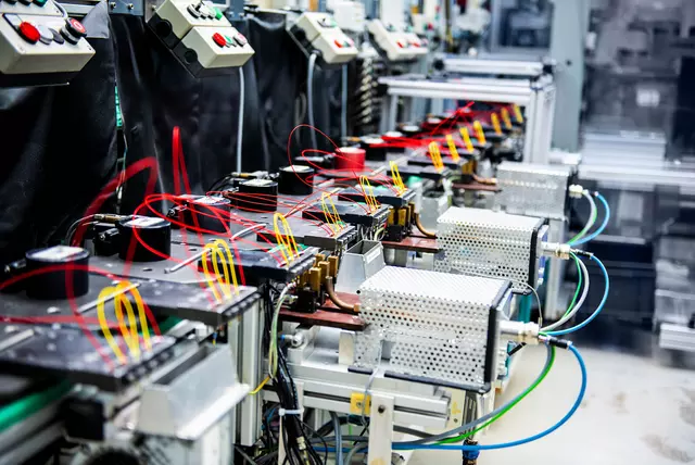
PTC plant
PTC stands for 'positive temperature coefficient' and is a temperature-dependent resistor. The fully automated system in Forchtenberg stands for high quality and quantity production of PTC sensors in customer-specific versions.
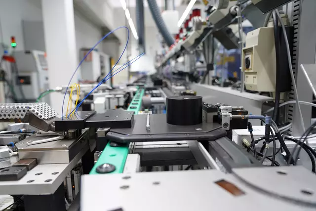
Good morning, machine!
7:00 a.m., Volker Wassermann enters the room to the PTC system for the shift change. Click, click, clack, hiss, clack. The sound of the machine, which runs around the clock in 3-shift operation, could perfectly provide the basic melody for a hit by the electro-pop band KRAFTWERK. The machine is strictly secured: Not just anyone is allowed in here. Valuable company secrets are hidden in the complex production of the PTC sensors.
Cool down: PTC motor protection
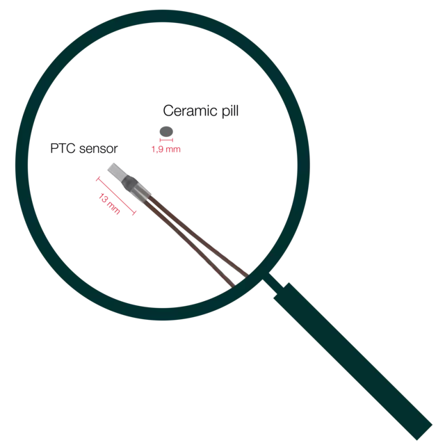
“Motor protection only works with reliable temperature monitoring. The physical background is simple: the PTC contains a small ceramic pill that increases its resistance when hot. As a result, the motor protection device notices that the heat in the motor winding is increasing - and switches off at the desired set value. This protects the motor from overheating and allows it to cool down again,” says Wassermann, explaining the basic principle. “What is not so simple: PTC sensors are located directly in the motor winding and are very small. The core, the ceramic pill, has a diameter of only 1.9 millimeters and a thickness of 0.5 millimeters. How do you manage to produce consistently high quality in this fine range? And still produce high quantities? That was the big challenge when developing the PTC system,” explains Wassermann.
At KRIWAN, the production of the small, fine PTC sensors has grown like an organism with the system that produces these sensors. This is where mechanical engineering becomes a creative achievement: how do you translate more than 20 hand movements on the smallest components into a machine? At the end of the 1970s and beginning of the 1980s, Mr. Kriwan was driven by the vision of advancing his then 10-year-old company with the automated production of PTC sensors. Due to the manual production of PTCs, the quality fluctuated. Not everyone has the dexterity to process the small PTC components flawlessly - and certainly not for 8 hours a day. The quality needed to be improved through automated production steps, also in order to be able to meet market demand through higher quantities.
That was easier said than done: no machine manufacturer in Germany could build a machine that could fix a tiny pill with a diameter of 1.9 millimetres between two wires long enough for them to be soldered cleanly.

PS on the PTC production line!
Ms. Kübler and Mr. Kober still remember exactly how PTC production worked back then: “I was allowed to pull cables into the workpiece carriers. We stripped the insulation, we galvanized them, we inserted them by hand,” recalls Ms Kübler.
“We initially had the template from Siemens. But here we realized that it wasn't working properly. We didn't know what the problem was, so we started to check every single sensor again,” says Hans Kober, electronics engineer and has been with KRIWAN since 1976. “It was a complex procedure. We built measuring machines in which the PTCs were inserted, tested and decided: 'good or bad'. The demand from our customers continued to grow. And at some point, Mr. Kriwan said: 'Now we'll make them ourselves! At this point, the manufacturer Siemens was supplying individual pills. So not prefabricated, but individual disks,” recalls Kober. “It was quite a process until they agreed to let us have them. After all, it was their know-how that they wanted to keep in order to share in the sales. Mr. Kriwan then did the first tests himself as usual: with rubber and two wires and intermediate clamps - until he then decided 'now we'll use a clothespin, it works like a workpiece carrier, you can clamp the wires in between',” says Kober. Little by little, all the problems were solved - and eventually the competition was left behind.

Circuit board placement machine (SMD machine)
The SMD placement machine places components on the surfaces of circuit boards, also referred to as PC boards. SMD means ›surface mounted device‹. The fitting of the circuit board comprises the placement of components on the circuit board as well as the following work steps:
1) Applying solder paste, which consists of tin particles and flux, by means of stencil printing.
2) Placing components into the solder paste on the circuit board.
3) Soldering process of the circuit board.
Mr. Bauer, what exactly happens in the SMD system?
We receive the PCBs that need to be tested from the manufacturer. Our job is to assemble these PCBs according to customer requirements. The data matrix code, which is burned in, is stored with the order data that is important for us. The printed circuit boards are produced as a composite panel. This means that several individual PCBs are arranged next to each other to form a large overall PCB. The bare PCB is fed into the SMD machine first. The surfaces are still unprinted. Before assembly, the connection surfaces of the SMD components on the PCBs are printed with solder paste using stencil printing.
What do you need the solder paste for?
We set the thickness, select the appropriate programs and the system ensures that the solder paste is applied. Solder paste is like porridge. In principle, it is small balls of tin and flux that are mixed into a mass. The stencil is clamped into the frame. The circuit board is pressed up against the stencil, as in screen printing. When the system has approved the whole process, it removes the PCB. The thickness is as thick as the stencil specifies. After the soldering paste has been applied, the PCB goes on to the placement machine for SMD placement.
How do the SMD components get onto the PCB?
The components are located on the rollers or in bars. A left and right head is used for placement. The fast head can hold and place up to 8 components. Intelligent software systems ensure that components cannot be mixed up.
And how are the components attached?
The assembled PCBs are placed in the oven after a quality check. In principle, this is a large convection oven with different temperature zones. First comes the warm-up phase: the PCB and the solder must be at similar temperatures to ensure a proper connection. Then comes the maximum temperature zone: the melting point of the soldering compound. This is where the flux evaporates.
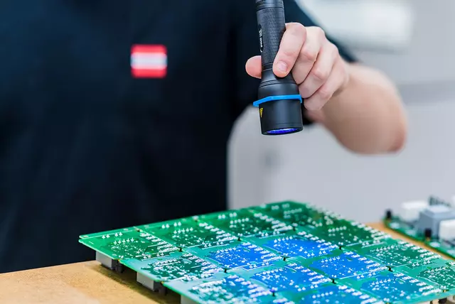
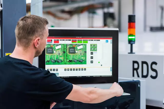
Finally, the finished product is optically inspected with a camera. This so-called AOI inspection (Automatic Optical Inspection) makes an optical comparison of the areas in which the components should be located. If there are any deviations, I am informed of the exact error pattern and can then correct the error or reject the PCB.
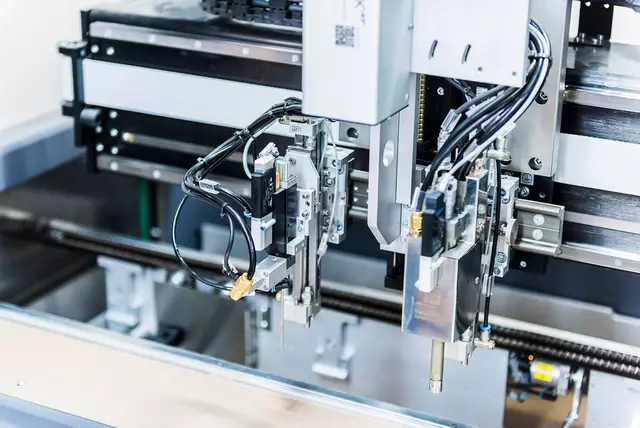
Selective painting system
Fully automated painting and drying line for the surface finishing of electronic assemblies with a capacity of 5,500 units per day.
Where should he coat, where is he allowed to coat, where is he not allowed to coat? Michael Miron, department manager of
placement series production, knows all about the coating systems at KRIWAN. He is also an expert in selective coating systems: the system that can select and coat specific areas fully automatically.
Mr. Miron: What kind of coating options are available at KRIWAN?
At KRIWAN we have 3 types of coating systems: Firstly, the dip coating system, in which the PCB must be fully immersed. In this process, everything is completely coated. Secondly, there is manual coating: here the coating is applied with a brush - this is also selective - but it takes a long time and every board looks different. Here, a lot depends on the training and practice of the employees. Last but not least, there is the selective coating system, which works according to the Industry 4.0 standard. Every PCB should look the same and the data relevant to the quality of the PCB should be stored for each PCB. The importance of selective painting can be seen in relays, for example. A relay is constructed in such a way that there is a chamber inside where a switch switches back and forth. Heat is generated here. When the whole thing cools down, colder air is created, it draws in the paint, covers the button and renders it inoperable. This can be avoided by leaving out areas to be painted.
Why do you varnish at all and with which varnishes?
A layer of lacquer is like a second skin. The lacquer additionally fixes the components to the circuit board and even if the devices are shaken or exposed to vibrations, they do not come loose. In addition
the varnish provides protection against dust and moisture and improves the conductivity of the PCB. There are a huge number of different varnishes from which you have to choose the right varnish for your application.
How is the system set up?
The system consists of various individual machines that are combined to form a coating line. The core of the system is the paint booth, which is responsible for coating. The largest single machine is the drying oven, which can dry the paints either by heat - using the convection method - or by infrared. When drying using only heat, there is a risk that the paint only dries on the outside and is still liquid on the inside. Just like pudding. The combination of direct heat and infrared dries from the inside and outside, ensuring that the paint hardens completely.
Do you have further questions or comments about the blog post? Please contact us!