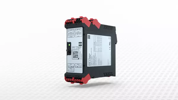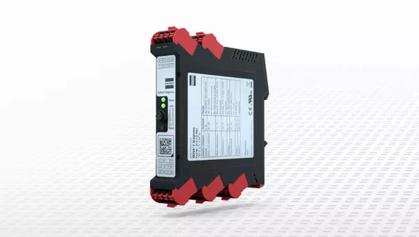
The solid all-round protective relay with a large number of sensor inputs for monitoring motor temperature, bearing temperature, leakage, vibration and voltage. The INT69 YF Diagnose EXTENDED differs from the STANDARD version because it provides an additional input for vibration measurement and a warning relay. Protective functions and behavior can be flexibly adjusted to the application through parameterization. The pump protection relays are particularly suitable for monitoring pumps, pump systems and submersible mixers in the water and wastewater industry.
| Article number | Power supply |
| 20 A 701 P081 | 24 V~/⎓ 50/60 Hz |
| 22 A 701 P081 | 100-240 V~ 50/60 Hz |
Find all important information about your product.
The INT69 YF Diagnose is a universal and versatile protection relay. The following inputs and outputs are available for monitoring electrical components:
| Terminals | Inputs and outputs |
| L/L+, N/L- | Supply voltage |
| T1, T2 | Motor temperature (PTC, Pt100, Pt1000, bimetal, external relay contact) |
| T3, T4 | Temperature 1 (PTC, Pt100, Pt1000) |
| T5, T6 | Temperature 2 (PTC, Pt100, Pt1000) |
| E1+, E1- | Leakage 1 (resistance measurement) |
| SC1, SC2 | Switching input (float switch, external reset) |
| I+, I- | Analog input 0/4-20 mA |
| FE | Functional ground |
| L1, L2, L3 | Phase monitoring with phase sequence, phase failure, phase asymmetry, undervoltage and overvoltage |
| 11, 14, 12 | Relay 1 |
| 21, 24, 22 | Relay 2 |
Parametrization enables protection functions and response settings to be adapted flexibly to suit the application. The INT69 YF Diagnose saves operating and fault data in a nonvolatile memory. This data can be read out and evaluated for diagnostic purposes. Parameterization and diagnostics are possible via the built-in diagnostic port (DP) using the INTspector app and with separately available accessories. This protection relay device is used primarily for the protection of pumps and agitators.
Supply voltage 22 A 701 P081 20 A 701 P081 |
100-240 V ~ 50/60 Hz ±10 % 9 VA 24 V ~/⎓ 50/60 Hz ±20 % 7 VA |
| Permissible ambient temperature Ta | -30 °C ≤ Ta ≤ +70°C |
| Permissible humidity | 0-95 % r.h., non-condensing |
| Maximum usage height | 2000 m |
Temperature measuring circuit, bimetal / external relay contact – Type – Contact suitable for – Max. line length |
for an NC contact 24 V ⎓ 20 mA 30 m |
PTC temperature measuring circuit – Type – R25, total – RTriggering, static – RReset – Short circuit monitoring – Break monitoring – Applied voltage – Motor temperature – Temperature 1 – Temperature 2 – Max. line length |
1-9 PTC sensors according to DIN VDE V 0898-1-401 in series <1.8 kΩ 4.5 kΩ ±20% 2.75 kΩ ±20% <20 Ω >20 kΩ
24 V ⎓ 5 V ⎓ 5 V ⎓ 100 m |
Pt100 temperature measuring circuit – Measuring range - 50… +300 °C – Resolution – Accuracy – Short circuit monitoring – Break monitoring – Applied voltage – Motor temperature – Temperature 1 – Temperature 2 – Max. line length |
- 50… +300 °C 1 K 5% of the ohmic value <20 Ω >400 Ω
24 V ⎓ 5 V ⎓ 5 V ⎓ 100 m |
Pt1000 temperature measuring circuit – Measuring range – Resolution – Accuracy – Short circuit monitoring – Break monitoring – Applied voltage – Motor temperature – Temperature 1 – Temperature 2 – Max. line length |
- 50… +300 °C 1 K 5% of the ohmic value <20 Ω >2.3 kΩ
24 V ⎓ 5 V ⎓ 5 V ⎓ 100 m |
Leakage measuring circuit – Type – Measuring range – Resolution – Accuracy – Applied voltage – Max. line length |
Resistance measurement between electrode pairs 5 kΩ – 1.5 MΩ 1 kΩ ±(1 kΩ + 10 % of MV) Approx. 24 V ~ 100 m |
Switching input – Type – Contact suitable for – Max. line length |
For a floating NC or NO contact (e.g., reset button) 24 V ⎓ 20 mA 100 m |
Analog input – Type – Applied voltage – Measuring range – Resolution – Accuracy – Current limitation – Max. line length |
0…20 mA / 4…20 mA current signal 24 V ⎓ +5 % / -25 % 0…20 mA 0.1 mA ±(2,5 % of MV) 30 mA, short-circuit-proof 100 m |
Phase measurement - Operation with FI - Measuring range phase-to-phase - Resolution - Clock frequency range - Type. Clock frequency - Accuracy sinusoidal drive - Accuracy FC operation - Max. Cable length |
Suitable 20-100 Hz~ 60-690 V~ ±10 % 1 V 2-16 kHz 8 kHz ±(1 V +2.5 % of measuring range) ±(1 V + 5 % of measuring range) 3m |
Interface - Max. cable length | Diagnostic port (DP) 10 m |
| Reset of lock or restart delay | - Option 1 Mains reset > 5 s - Option 2 External reset at the switching input > 5 s Only possible if there is no longer an error |
Relay 1, Relay 2 – Contact - Rated data (UL/CSA) - Rated load (ohmic) – Mechanical service life |
240 V ~, 2.5 A C300 Min. 24 V ~/⎓ 20 mA Max. 240 V~ 2.5 A C300 250 V~ 10 A Approx. 1 million cycles |
| Degree of protection as per EN 60529 | IP20 |
Connection type – General |
Tension spring connection (push-in) 0.2-2.5 mm2 |
| Housing material | PA 66 GF 30 |
| Fixing | Control cabinet housing (basic grid 45 mm), clippable on to 35 mm standard rail as per EN 60715 |
| Dimensions | See dimensions in mm |
Weight – 22 A 701 P081 – 20 A 701 P081 |
Ca. 300 g Ca. 300 g |
| Test regulations | EN 61000-6-2, EN 61000-6-3, EN 61010-1 Overvoltage category III Degree of pollution 2 |
| Approval | UL File No. E473026 cURus |
Compare our products and find the right protection relay for pumps.
| INT69 PYF Diagnose Premium | INT69 YF Diagnose EXTENDED | INT69 YF Diagnose STANDARD | INT69 F Diagnose BASIC | INT69 EXF2 Diagnose BASIC EX | |
| Motor temperature | PTC, Pt100, Pt1000, bimetal, external relay contact | PTC, Pt100, Pt1000, bimetal, external relay contact | PTC, Pt100, Pt1000, bimetal, external relay contact | PTC, Pt100, Pt1000, bimetal | - |
| Temperature 1 | PTC, Pt100, Pt1000 | PTC, Pt100, Pt1000 | PTC, Pt100, Pt1000 | PTC, Pt100, Pt1000, bimetal | PTC |
| Temperature 2 | PTC, Pt100, Pt1000 | PTC, Pt100, Pt1000 | PTC, Pt100, Pt1000 | - | Bimetal |
| Leakage 1 | Conductance measurement | Conductance measurement | Conductance measurement | Conductance measurement | Conductance measurement |
| Switching input | float switch, external reset | float switch, external reset | float switch, external reset | - | - |
| Analog input | 0/4-20mA | 0/4-20mA | - | - | - |
| Phase monitoring | Phase failure, phase sequence, phase asymmetry, undervoltage and overvoltage, run detection | Phase failure, phase sequence, phase asymmetry, undervoltage and overvoltage, run detection | Phase failure, phase sequence, phase asymmetry, undervoltage and overvoltage, run detection | Run detection | Run detection |
| Current monitoring | Current transformer INT185 | - | - | - | - |
| Power measurement / -monitoring | Apparent, active and reactive power, Cosφ, Underload, Overload | - | - | - | - |
| Relay 1 | Alarm, Warning | Alarm, Warning | Alarm, Warning | Temperature | Temperature |
| Relay2 | Alarm, Warning | Warning, Warning | - | Leakage | Leakage |
| Interface | Diagnostic Port (DP) Modbus RTU (RS485) | Diagnostic Port (DP) | Diagnostic Port (DP) | Diagnostic Port (DP) | Diagnostic Port (DP) |
| Housing width | 45mm | 45mm | 45mm | 22.5mm | 22.5mm |
| Reset function | Mains reset / external reset / Modbus reset | Mains reset / external reset | Mains reset / external reset | Reset button / external reset / mains reset | Reset button / external reset / mains reset |
| Supply voltage 100 – 240 V ~ 50/60 Hz | 22 A 721 P081 | 22 A 701 P081 | 22 A 700 P081 | 22 A 712 P081 | 22 A 713 P081 |
| Supply voltage 24 V ~/⎓ 50/60 Hz | 20 A 721 P081 | 20 A 701 P081 | 20 A 700 P081 | 20 A 712 P081 | 20 A 713 P081 |
Look at the monitoring modules, the options and examples of use of our pump protection relay.
| Monitoring module | Options | Example of use | |
| 1x | Motor temperature | PTC, Pt100, Pt1000, Bimetal, external relay contact | Motor temperature sensor |
| 1x | Temperature 1 | PTC, Pt100, Pt1000 | Bearing temperature, winding temperature, mechanical seal, etc. |
| 1x | Temperature 2 | PTC, Pt100, Pt1000 | Bearing temperature, winding temperature, mechanical seal, etc. |
| 1x | Leakage 1 | Resistance below, exceed resistance | Resistance measurement between leakage electrodes, resistance measurement from leakage electrode to pump housing |
| 1x | Switching input | Switching input NO, switching input NC, reset | Float switch, reset button |
| 1x | Analogue input | 0 - 20 mA, 4 - 20 mA | 2-wire sensors without own power supply: vibration sensor, pressure sensor, etc. |
| 1x | Phase monitoring | Phase sequence, phase failure, phase asymmetry, undervoltage, overvoltage, run detection | Measuring range phase-phase |
| 1x | Relay 1 | Alarm, Warning | Shutdown or warning when exceeding limit value or when falling below limit value (e.g. motor temperature, temperature 1, temperature 2, leakage 1, etc.) |
| 1x | Relay 2 | Alarm, Warning | Shutdown or warning when exceeding limit value or when falling below limit value (e.g. motor temperature, temperature 1, temperature 2, leakage, etc.) |
| 1x | Interfaces | Diagnostic Port (DP) | Connection of a USB gateway (INT600 DU Gateway) or a Bluetooth gateway (INT600 DB Gateway) to use the INTspector App, Connection of Modbus gateway (INT600 DM Gateway) for retrieval of parameters and integration into the system control |
| 1x | Reset function | Mains reset, external reset | Resetting the interlocked shutdown as soon as there is no longer an error |
Technical data sheet until 28th February 2022
Brief instructions as of 1st August 2024
Brief instructions until 31st July 2024
Modbus table as of 1st August 2024
Modbus table until 31st July 2024
Parameter table as of 1st August 2024
Parameter table until 31st July 2024
Tender specification
The protection relay monitors temperatures (3x inputs for PTC, Pt100, Pt1000 or bimetal), leakage (2x inputs for conductivity measurement or switching input) and voltage. An alarm relay provides the necessary operational safety.
The INT69® YF Diagnose EXTENDED differs from the STANDARD version by an additional analog input (0/4-20mA) and a second relay for warnings.
You need an end device, such as a laptop, cell phone or tablet with the KRIWAN INTspector App installed and a KRIWAN USB or Bluetooth gateway to establish the connection between INT69 YF Diagnose and end device.
For quick and easy status indication and troubleshooting, a blink code is output via an LED on the front of the protective relay housing. This consists of a cyclic flashing sequence which can be looked up in the data sheet.
For a more detailed view, the KRWIAN INTspector App is available. The diagnostic data provides an overview of the operating behaviour of your pump. Events, operating times, switching cycles and current measured values are displayed and help with detailed analysis on site.
All events such as warnings, errors or messages are stored in a non-volatile internal memory and can be viewed via the INTspector App. The event memory contains the 20 most recent events with time and date. There are also counters for all events.
No, the INT69 YF Diagnose is designed for monitoring three-phase motors.
Submersible pumps and agitators, for example, are often already equipped by the manufacturer with moisture electrodes that can be monitored with the INT69 YF Diagnose at E-, E+. These have the function of monitoring against penetrating medium or dry running. For this purpose, the resistance (conductance) between the two electrodes is measured. Depending on the application, the operating mode must be set to resistance exceeding or resistance falling below.
There are several options, such as disconnecting the supply voltage >5s of the INT69 YF Diagnose (mains reset). Or by connecting an external reset button (normally open contact) to the switching input SC1, SC2. The protection relay can only be switched back on after an interlocked switch-off after a reset has been done and if there is no longer an error.
The INT69 YF Diagnose has an alarm and a warning relay. If an error or warning is detected, the alarm or warning relay drops out. For each input, it is possible to parameterize the warning, set point and switch-off values, tripping and restarting delays or an interlocked switch-off. Both relays are always active as soon as an input is actively monitored. The two relays operate according to the closed-circuit current principle.
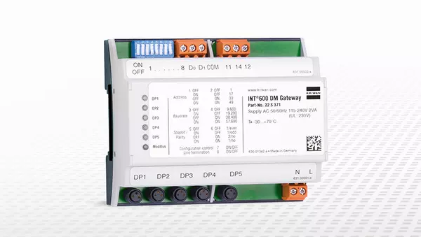
To integrate the KRIWAN protection relay into your control system, you need an INT600 DM Gateway that converts the pump operating data into a Modbus protocol (Modbus RTU).
The packaging contains the respective protection relay (depending on the voltage variant AC/DC 24V or AC 100-240V) and the brief instructions. In addition, terminating resistors for Modbus communication are included in the scope of delivery. The INT185 Current Transformer with a measuring range of up to 100A and up to 250A is not included in the scope of delivery and must be ordered separately.
All KRIWAN pump protection relays are delivered with a factory setting. The one for the INT69 YF Diagnose can be found on the product page in the download area as a parameter list. The parameterization can be individually adapted to your application during installation and commissioning using the KRIWAN INTspector App.
We are happy to help you with your questions. Simply use the contact form on our homepage and send us a request. Our customer support will get in touch with you.
Find the right accessories for our products.
Connect your KRIWAN diagnostic devices via Modbus gateway
Connect your KRIWAN diagnostic devices to the INTspector app via USB gateway
Connect your KRIWAN diagnostic devices to the INTspector app via Bluetooth gateway
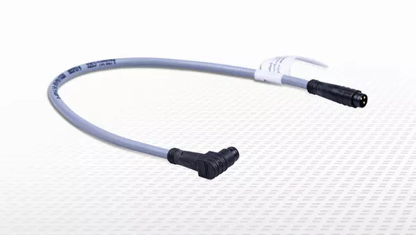
For the right connection between your protection device and the gateway
For parameterizing your device and reading out all important data
Do you already know our extensive product range?
Learn more