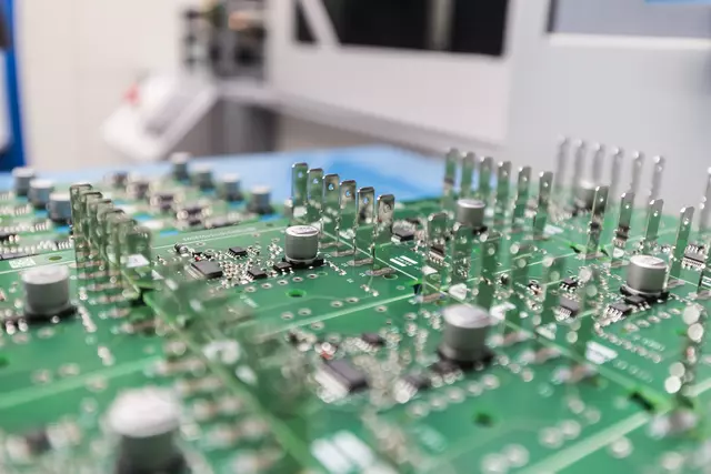
 Protection relays
A KRIWAN protective relay reliably protects your electric motor from thermal overload and overheating, and has done so for over 50 years. Probably the best known KRIWAN protection relay is our classic INT69. The KRIWAN INT69 monitors the motor temperature using temperature sensors such as PTC or AMS. In addition, KRIWAN offers different types of protection relays for special requirements in refrigeration and air conditioning. For example, in addition to motor temperature, KRIWAN protective relays can monitor other operating parameters such as oil temperature, oil flow, oil level, or even phase.
The latest generation of protective relays includes our multifunctional relays, which were developed especially for the high demands of the water and wastewater industry. Up to 7 sensor inputs are available to the user: Motor temperature, two further temperature inputs, leakage, phase monitoring, current intensity and power measurement by means of current transformers.
In addition to the classic monitoring of the motor temperature by means of PTC, KRIWAN also offers a range of other parameters that can be monitored using the various KRIWAN protective relays. Together with you, we will find the suitable protective relay.
The abbreviations, e.g. I, U, Y, etc., are part of the product designation, e.g. INT69 UY, and provide insight into the functional scope of the respective device variant.
Y
Protective relays with the phase monitoring function are suitable for reliable monitoring of three-phase networks. In doing so, systems are protected against phase failure, phase asymmetry and incorrect phase sequence.
L
Protective relays with oil monitoring function are used in combination with other KRIWAN devices such as the INTT250 to monitor the oil differential pressure. Monitoring of the oil level is possible in combination with the KRIWAN level sensors INT275 to INT279.
U
Protective relays with the voltage monitoring function are used to monitor overvoltage and undervoltage. The voltage limits can be selected individually as required.
I
For current monitoring with the INT69 I or INT89 I, the INT185 KRIWAN current transformer is also required. This allows the system to be protected against overcurrent and undercurrent. The switch-off values can be set individually as required.
P
The INT185 KRIWAN current transformer is required for power measurement. The measured quantities of current, voltage and the calculated phase angle φ are used to calculate the absorbed active and reactive power of the motor. Likewise, the apparent power is determined as an intermediate result. All three powers and the cos phi (collective quantities of the overall system) are output cyclically as rms values via DP.
F
The resistance value is measured between the leakage electrodes (electrode - housing is the most common application or electrode - electrode).
TM
The timer function is a restart delay, for example after faults, e.g. if the compressor has become too hot and therefore takes longer to cool down. With KRIWAN diagnostic devices, the restart delay can be parameterized individually.
Find the Right Protection Relay for Your Application
Protection relays serve to detect faults and prevent damage in electrical systems. Different types of protection relays are available, tailored to different applications and protection concepts.
Motor protection devices have to be adapted and adjusted to the respective application. Today, this is usually done using potentiometers and switches on the relay or by adapting the hardware and software at the manufacturer of the motor protection relay.
If the motor protection relay is equipped with potentiometers, it can be easily adapted to the application. However, this is precisely where a major disadvantage lies. In the event of a fault, the potentiometers can be easily manipulated so that the motor runs again. The protective function is thus no longer given and safe operation of the system is no longer guaranteed.
KRIWAN meets this challenge with a digital solution. The new generation of KRIWAN electronic protection relays features an interface that allows the protection relay to be connected to a smartphone, tablet or PC via USB or Bluetooth and parameterized using the INTspector App developed specifically by KRIWAN.
Rights management enables the plant manufacturer to define precisely which parameters may be changed by the service technician on site, for example. Manipulation of the individual safety parameters is thus prevented. At the same time, all events and setting changes are documented by the software and can be traced at any time.